
How to Read PCB Schematics for Beginners
Published - 4 weeks ago
All articles Electronics Tutorials
For anyone new to electronics, reading a PCB (Printed Circuit Board) schematic often feels like reading a map in a foreign language. Once you understand the basic symbols, though, a schematic becomes the single most important tool before soldering any component.
The first step is recognizing basic component symbols: resistors are drawn as boxes or zigzags, capacitors as two parallel lines, and diodes as a triangle with a line at the tip. Each symbol is usually labeled like R1, C2, or D3, referring to the component's physical position on the board.
After the symbols, pay attention to the connecting lines (traces). Lines meeting at a point marked with a dot mean they are electrically connected, while lines crossing without a dot mean they are not. Misreading this is the most common cause of beginner assembly failures.
Finally, get in the habit of tracing the power (VCC) and ground (GND) lines before anything else. Understanding the power flow makes it far easier to track down problems when a board won't turn on or a component runs unusually hot.
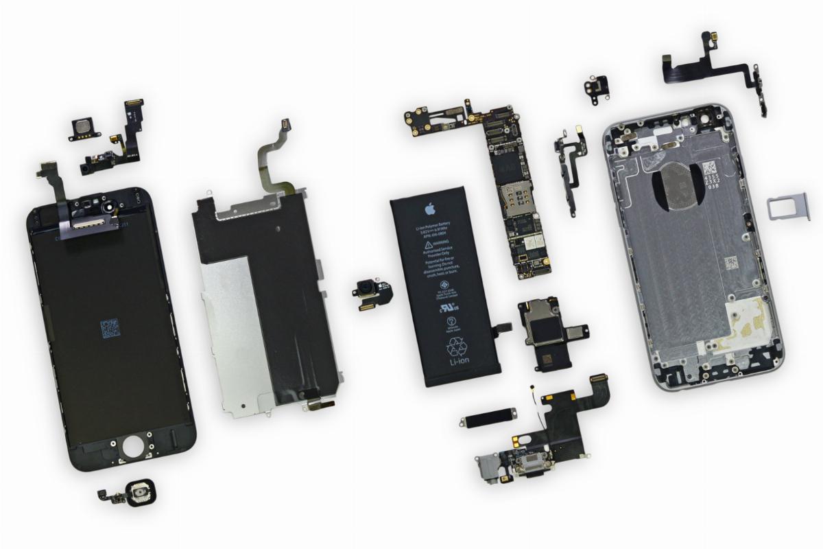
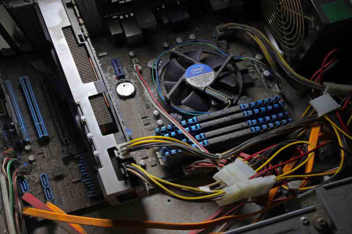
The best practice is to take apart schematics from simple projects like an LED blink circuit or a battery charger, then compare them against the physical board. The more you practice, the more reading schematics becomes a reflex — just like an experienced electronics engineer.
Related Articles
Written by

0 Comment
Popular Categories
Getting Started Tips
2Electronics Tutorials
3Cybersecurity
2Internet of Things
2Latest Articles

Understanding Phishing Attacks and How to Avoid Them
Phishing is one of the most common digital scam methods — attackers po...4 weeks ago

Five Must-Have Phone Apps for Beginner Electronics Technicia...
Before rushing to buy expensive measuring tools, there are several fre...4 weeks ago
How to Store and Maintain Your Soldering Iron for Years of U...
A properly maintained soldering iron can last for years, while one tha...4 weeks ago